

Training & Support
Looking for Advanced360? We’re improving your Advanced customer portal to make it even easier for you to download software, book training, raise support tickets – and much more…
For now, you’ll find familiar Advanced360 features here.


Request a brochure
You’ll find brochures in the relevant product section:
Go to Products, choose the relevant product and scroll to the brochure section.

Request approved partner certificates
Request the approved partner certificate by completing this form.


View datasheets
You’ll find datasheets in the relevant product section:
Go to Products, choose the relevant product and scroll to the datasheets section.

Watch ‘How to’ films
Our series of 'How To' films help answer common technical questions - discover them on YouTube.
Consultant Specifications
You’ll find consultant specifications in the relevant product section:
Go to Products, choose the relevant product and scroll to the documentation section.

Slide in labels
You’ll find slide in labels in the relevant product section:
Go to Products, choose the relevant product and scroll to the documentation section.
Customer Service
The Advanced Customer Service team is here to help make ordering from us easy.
Whether you have product queries, need support with an order or have questions about deliveries, we’re available to provide advice and updates whenever you need them.
You can reach the team at any time by emailing: customerservices@advancedco.com
or by calling: +44 (0)345 894 7000 Option 1 | Option 4 during UK office hours.

Technical Support
Our team of technical support engineers is on hand to help you get the most out of your Advanced equipment.
Available by phone or email, we’re here to answer your questions and make sure that using our products is easy and fuss free.
Whether you need quick setup advice whilst on site or help planning a complex network, we have the expertise to ensure your fire protection solution is fit for purpose and provides long-term safety and peace of mind.
You can reach the team at any time by emailing: tech@advancedco.com
or by calling: +44 (0)345 894 7000 Option 2
Tech Support Tips
We love to share our expertise with our customers. Here you'll find the answers to some common support queries we receive and tips to help you get to grips with the full range of features your Advanced equipment offers.EN54-13 is used as an early warning system to identify potential weaknesses in a fire system design or installation where voltage/current demands are too high. The CIE calculates this demand using Ohms Law (V=IR) to ensure that a system design can operate within acceptable parameters.
The characteristics needed to satisfy EN54-13 are as follows:
- Loop cable resistance – determined by cable variation (1.5mm cable – 1km & 2.5mm cable –
2km) - Typical voltage output from loop card – 24vdc-32vdc
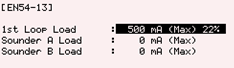
- Loop current driver capacity – 500mA (max)
- Permissible voltage drop based upon resistive load – 7v (max)
If loop calculations exceed the maximums stated above, the CIE will report a ‘High Resistance Fault’.
Results can be checked on the panel using the menu option Access Level 3 > Next Menu > EN54-13, as shown in the image below.
For full details of CIE monitoring, please download our in-depth tech tip. You can also download our application note giving a full overview of EN54-13.
The Advanced ‘Trace Logging Mode’ can track, trace and fix those niggling data corruption faults that sometimes arise from the following installation issues:
- Induced Alternating Current (AC)
- Earth Fault
- Earth Potential Difference
- Water Ingress
- Faulty Device
- Multi-Core Cable
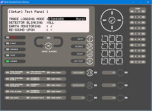
The Trace Logging option has three different operating modes: Standard, Standard+ and Diagnostic, which you can enable through the panel menu options by navigating to the ‘Commission > Setup’ menu identified below.
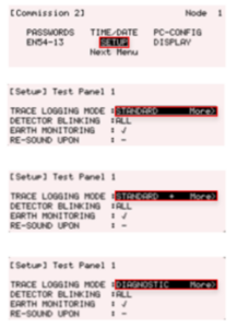
A panel typically uses the ‘Standard’ event logging mode, but enabling the Standard+ or Diagnostic modes will let you see any underlying/background transitory activity in more detail and help you to diagnose problems more quickly and easily on site.
Track, trace and fix earth faults using the onboard multi-meter as detailed in our downloadable step-by-step procedure.
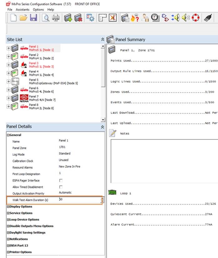
The one man walk test feature on all Advanced panels provides a 10-second activation in which sounders will automatically silence. By default, relays do not operate.
You can extend the duration of the 10-second activation up to a maximum of 60 seconds using the MxPro and Axis EN PC config tool. This is ideal for applications using voice-type sounders.
To extend the duration:
Locate the individual panel under the ‘Site List’, and then update the ‘Walk Test Alarm Duration’ which you’ll find under the ‘General’ tab. See the image below for further details.
Is the default Service Due Date on your panel set to a date in the near future? If so, the panel will enter a fault condition when this date is reached to alert the site operator that a service visit is overdue.
To pre-empt this and prevent your panel going into fault, you can set the Service Due Date reminder using these easy steps:
- Tools > Commissioning (note on the MxPro 4 simply select Commissioning) and enter your Level 3 code
- Once in Level 3, select Next Menu > Setup
- Scroll down using the down arrow button and select the ‘Service Due Date’ option
- Enter an appropriate time and date for the next Service Due Date reminder
Please note that this feature can’t be disabled.
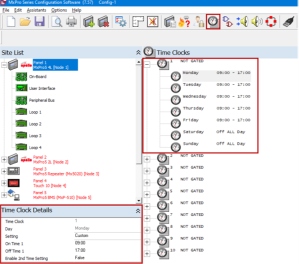
The MxPro 5 product range includes ten onboard programmable time clocks that can be used independently, or as part of a site-wide cause & effect strategy to control the operation of output modules across an entire network system.
Time clocks are most commonly used for class change, output control, detector mode change, investigation delays and as part of logical programming.
To program time clocks, use the options highlighted in the screenshot below:
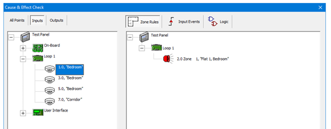
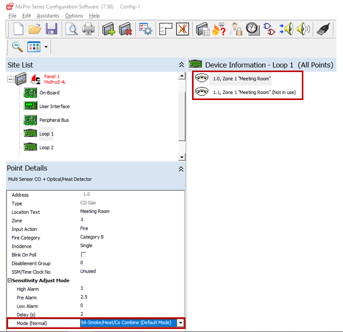
Do you want confirmation that your programming is correct when using our configuration software (PC-Net-003)?
If so, you can use the “Cause and Effect Check” option that’s built into our programming software. This allows you to confirm the outcome of an individual device activation. The results displayed will vary depending whether an input or output is selected as the source object.
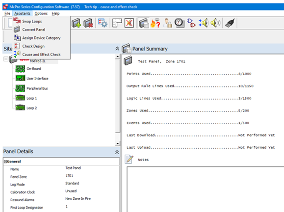
Outputs driven by inputs
Once in the “Cause and Effect Check” option, you can confirm that the output programming is correct by selecting a loop device from the left-hand window. The right-hand window will automatically display the input event results that have been assigned to drive that device. The options include results for zone rule, input event and logic statement programming.
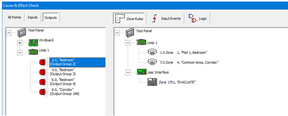
Inputs driving outputs
The same applies for inputs driving outputs. These can be confirmed by selecting a loop input device from the left-hand selection window, with results for the output device that will operate shown in the right-hand window. The options include results for zone rule, input event and logic statement programming.
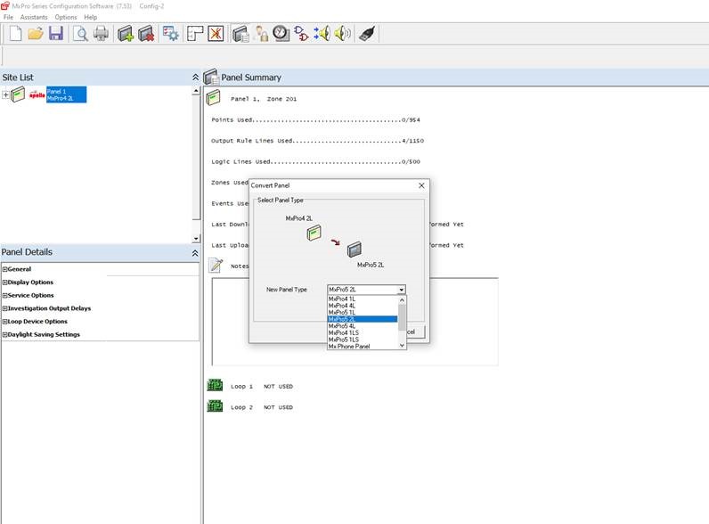
Replacing an old MxPro 4 for a newer MxPro 5 panel is as easy as 1,2,3. This process eliminates the need to reprogram the config from scratch, saving you valuable time.
To convert the panel, follow the three steps below:
1. Open your saved copy of the MxPro4 config.
2. Click on Assistants and select convert panel.
3. Select the correct number of loops for the MxPro 5 and click OK.
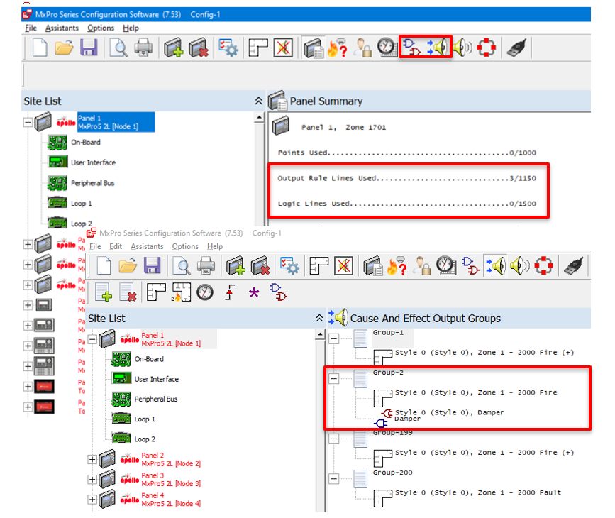
The MxPro 5 product range offers a vast array of powerful ’cause and effect’ programming options. A standard mapping version is available for less demanding projects, while the demands of more challenging sites are easily met by using flexible logic and programming options.
The MxPro 5 product range can accommodate up to 200 network panels per network, with support for 1150 lines of programming per panel. This makes it possible to deliver an extremely powerful client solution across one system, based on 230,000 lines of cause and effect mapping. Examples of both standard and logical mapping are shown below.
MxPro 5 panels can be used with Apollo, Hochiki, Argus Vega and Nittan (Evo) protocols.
Each Advanced panel must be connected to only one type of protocol from the four available. However, you can easily use panels supporting different protocols to build ‘multiprotocol’ networks across sites. This is a significant advantage when replacing panels in buildings where several fire detector protocols are present as it saves the cost of having to remove incompatible devices.
Our easy-to-use networking software lets you specify the protocol in use on a particular panel so that information can be shared across the network for seamless cause and effect.
To discover more about what’s possible by combining protocols, please contact our technical support team.
Ground troubles can be easily tracked, traced and fixed using Axis AX’s onboard multi-meter.
Identify the ground trouble via this menu option:
Access Level 2 > View > Panel > Local Hardware > Ground Volts
The standard/normal ground voltage value for Axis AX is shown below.
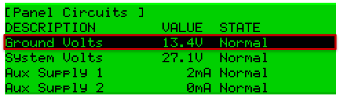
Should ground voltages exceed those provided above, this will result in a ‘high’ (positive to ground) or ‘low’ (negative to ground) fault.
To discover how to fix the identified fault on Axis AX, please download our step-by-step guide to the actions you need to take.
Optional key switches (volt-free) are available to be mounted on the MxPro 5 panel fascia plate. These are pre-wired with the appropriate 2-pin connector.
To install a key switch, follow these easy steps:
- Use a sharp knife to cut through the fascia label using the aperture profile as a template.
- Insert the key-switch mechanism and tighten the nut.
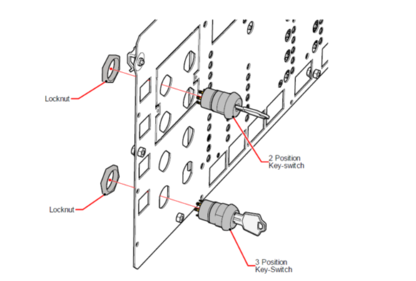
- Route the wiring as shown below and install the plug on the connector for the required switch
input position. The leads are a common length suitable for installation of the switch in any
position. - Fold up any extra cable neatly and apply a tie-wrap to hold in place.
- Use Level 3 panel access or the PC Tool to program the required function for each switch
input. - The fascia label is provided with a slide-in label pocket for a user text description.
- Slide the required insert label into the pocket to provide a description of the switch function.
- A standard access enable insert label is provided with Mxp-511 (key switch control) or we can provide a ‘Word’ template for printing out customer-specific text labels.

We'd love to discuss your training needs…
If you'd like to discuss course content, want to arrange group training at your premises or perhaps need to customise a course to suit your needs, please get in touch
Get in touch